![]()
|
|
Autoformer Volume Control FAQ Q
- What is an autoformer? A
- An autoformer (short for autotransformer) is a special type of transformer
with an especially simple winding arraignment. The simplicity means
that it can't be substituted for an ordinary transformer in most applications,
but when it can be used the result is a device with higher performance. To
be more specific, an ordinary transformer has separate primary (input)
and secondary (output) windings, while an autoformer shares some part
of the winding between the two.
Note
that the ordinary transformer provides DC isolation between the input
and output windings. In many applications this is an important feature. However, when DC isolation is not required
then an autoformer will often outperform an ordinary transformer. This
is because virtually all electronic devices exhibit some imperfections;
they are not ideal. But compared to an ordinary transformer, an autoformer
can often be made with fewer (or smaller) imperfections. The behavior
of an autoformer is often closer to ideal. You
might have noticed that the autoformer is a simple three-terminal device
with a common ground. This makes it a direct replacement for resistive
voltage dividers like potentiometers or stepped attenuators. Q
- Why use an autoformer volume control? I've been happy with a good
quality potentiometer. A
- The simple answer is that most people find that the autoformer volume
control sounds significantly better than even the best potentiometer
or stepped attenuator. And it's not a subtle difference; most people
report that the autoformer has such an open, effortless sound that they
would not consider going back to a resistive device. Exactly
why they sound better is still under debate, but one theory is that
it's because an autoformer doesn't attenuate by wasting energy. A fairly
good analogy can be made to the transmission in a car. If you need to
drive at a slow steady speed which method would you choose: (1) leave
the transmission in high gear and apply the brakes to keep from going
too fast, or (2) downshift into a lower gear that will allow the car
to go the desired speed with minimum effort? An
autoformer is essentially an electronic gearbox that operates without
wasting significant energy. Potentiometers and stepped attenuators adjust
the signal level by literally turning the excess signal into heat. On
the other hand, when an autoformer is adjusted for low volume level
it actually makes things easier for the source, much like a low gear
makes things easy for your car engine. It
becomes quickly apparent that the reflective load can be ignored in
this case since it is many multiples of the inductance in parallel with
it. Inductance gives you a impedance = 2*pi*Frequency*L(inductance) or
Z=2piFL. Its this simple formula that tells you what you need to know
about the load presented to the source.
Q
- What is the impedance presented to the source? A
- It is the reflected load in parallel with the inductive reactance
of the autoformer. When set for no attenuation, the reflected load is
simply whatever follows the volume control in the signal chain. However,
that load is cut in half (resistance is doubled) for every 3dB of attenuation. At -20dB the reflected load value is increased by a factor of 100.
At -40dB it is increased by a factor of 10,000 which is 10,000 times the
resistance!
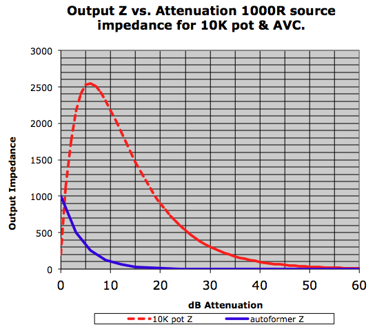
Q - What is the output impedance? A1 -The easy answer to this is to use the calculator below. Simply input your source impedance and adjust the slider to the expected attenaution and the output impedance will be shown.
A2 -The output impedance is a function of the source impedance driving it and the attenuation setting. Put simply... Worst case is at 0dB of attenuation where the output Z is = to the output Z of the source and it goes down as you attenuate. A more precise explanation is the output Z = Source Z / turns ratio squared. Assuming a 1K source and 6dB of attenuation we get the following: Z= 1000/4^2) or z=1000/16 or Z=62.5 ohms. A graph of the output Z of an autoformer quickly tells the story and you can see that as you attenuatte the output Z of an autoformer quickly approaches 0.
Q- How do I hook them up? A- Check out the AVC Wiring page Q
- What is the core material.? A
- HyMu 80 Q
- How does it differ from permalloy and mumetall? A
- The difference is primarily in the spelling, though mumetal contains
a Q-
Do I need to shield the autoformers from external fields? A
- In most cases, careful layout and construction makes this unnecessary.
Preferably, they should not share a chassis with other transformers.
If your layout or environment makes shielding necessary, we do offer
shielding materials. Typically, placing the autoformer in the
'shadow' of a single piece of foil is sufficient to shield from 50/60Hz
hum. Rarely is it necessary to completely enclose the device. Because
the foil has a very high magnetic permeability it should not be placed
as far as practical from the autoformers, preferably at least 1/2 inch.
A little experimentation might be necessary...
Q
- What is the frequency response? A - The frequency response on the low end is determined by the ratio of the inductance and the output impedance of the source. The frequency where the Zout of the source = 2*pi*F*L the response will be -3dB. The -1db point will happen at double the frequency of the -3dB point. The top end behavior remains consistent with any stacking method and exceeds 200khz on all attenuation settings. A
- 12V@20hz
Q
- what if I need more than 42db of attenuation. A - Custom units can be wound to 54dB of attenuation. Note that that is a 500:1 stepdown and may compromise the performance slightly. If you require that much attenuation you might want to examine the gain structure of your system. Q
- Can the units be wired for gain?
A
- Yes, some people report good results but be aware that wiring for
6dB of gain means that the source will see only 1/4 the inductance of
the full winding. Stacking the core with more interleave will recover
the lost inductance, though the ultimate success may depend on your
system and your requirements. It is also important to note the behavior
of the device when used for gain might not make measurement conscious
people very happy. We encourage experimentation and appreciate any and
all feedback. Q
- Do I need to load the secondary? A
- No, it is not necessary. But this shouldn't stop you from experimenting.
You might find that you prefer some additional load.
Q
- Will they work for balanced
attenuation.? A - They have been used with good results in balanced systems but it requires two autoformers per channel. If both the source and load adhere to the brodcast standard, a single autoformer will work. Q
- Can it be used with solid state,? A
- Absolutely. The lower output impedance generally makes for a very
good match. Recent feedback suggests that the benefits
in a solid state system seem to be greater than in tubed systems. Q
- What if I don't like the sound? A - We are proud to say that very few people have been anything less than thrilled by the sound. We are also proud to say that the few customers that have tried to sell their units have had no trouble at all. That's
about it for now, please check out the forum for more information.
|
|